 Home
About
Links
Home
About
Links
Robot Arm : Phase 2 - Let's kick it up a degree !
Posted 12/31/2008 by Emil Valkov
Contact:
Contact:
This is an evolution of my initial robot arm. I added an extra servo at the base, thus bumping up the degrees of freedom to 3. This introduces a new challenge as the arm moves in 3D now. To obtain 3D coordinates, I use 2 cameras and triangulate the 2D coordinates into 3D coordinates.
Here's a video showing the robot in action. I enlisted the help of my son as narrator; he was very eager to participate !
Hardware upgrades

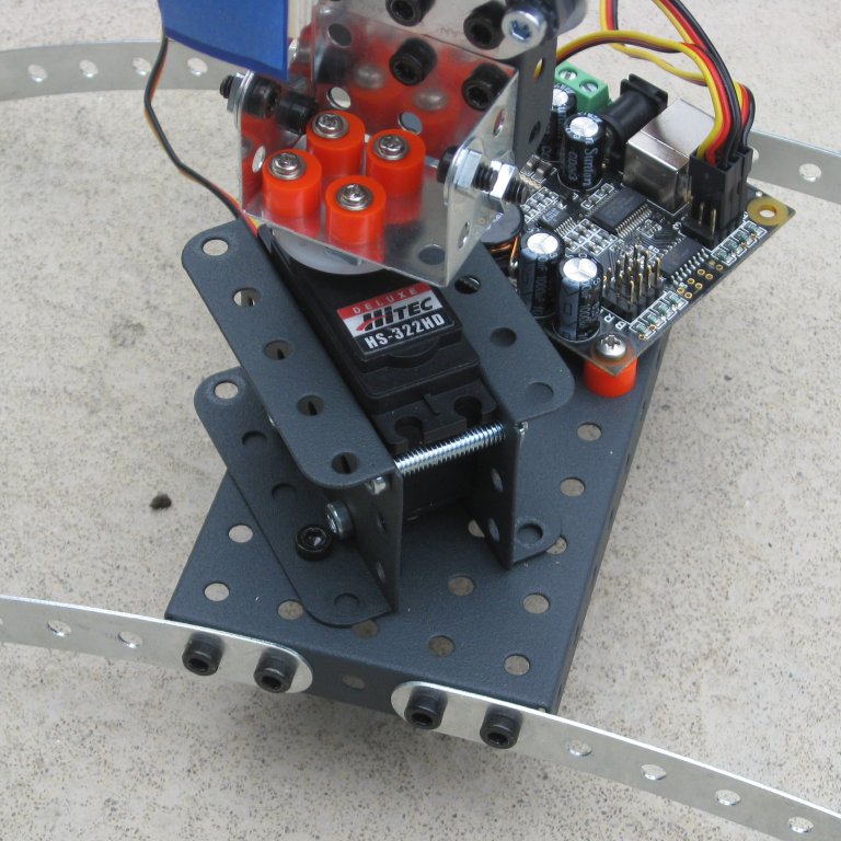
The first upgrade is of course the new servo at the base that adds the new degree of freedom.
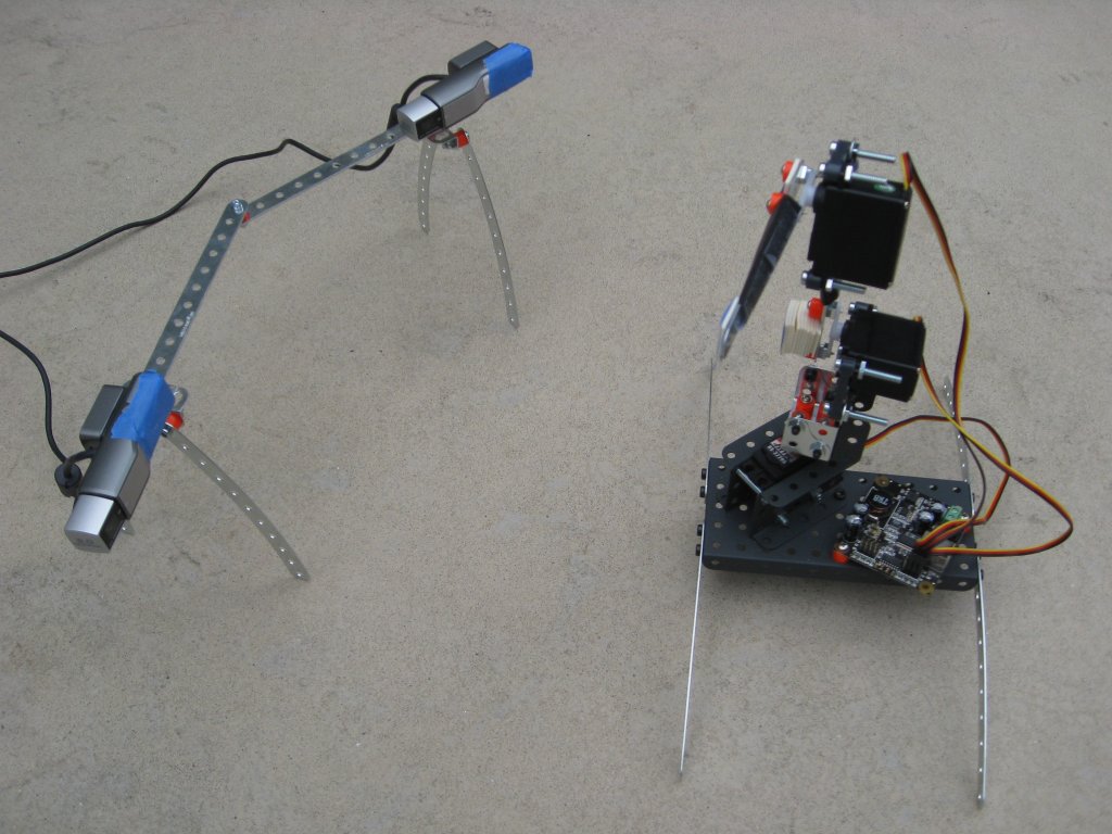
You can also see the 2 camera assembly, with the 2 cameras at an angle, both looking at the robot.
Also some minor changes: I coated parts of the arm with black paper, because those parts were very reflective and played tricks on the cameras.
The shoulder blue square has been padded to adjust its depth so that it's in the same plane as the other 2.
This wasn't a problem in 2D, and probably isn't in 3D either.
Still with so many opportunities to accumulate errors, this one was easy to fix.
RoboRealm
I use the same modules as before, except now I need to repeat them twice: once for each camera.
Set_Variable is used to copy the BLOBS variables into BLOBS1 and BLOBS2, so as to make the values from both cameras accessible at the same time to my program.
Then, finally, I use Mosaic to display video from both cameras side by side.
You can download the .robo file I used here.
3D Tracking
This image shows the same configuration as seen from 2 cameras, from 2 different angles.
Tracking is done similarly to phase 1, except all calculations are now done in 3D.
The circular trajectories we had are still circular but only in 3D space, when seen by the cameras, they appear elliptical.
You can see the green and blue circles whose tangents we need.
Added to the green and blue tangents, is a third red vector which shows the movement normal to the arm, and linked to movement of the base motor.
The green, blue, and red lines together form a Parallelepiped, that may help getting a rough idea of the 3 axis I use to project onto.
To imagine the lines properly in 3D, it may be useful to note that all the green and blue lines are all to the same plane, which is the plane on which the physical arm is on as well.
The red lines are perpendicular (or normal) to that same plane.
The big black dot is the target, which is placed 2 inches above the point[3] because we currently don't handle overlapping blue squares.
Code
The code was updated from the 2D math in the previous version to 3D.
Vector diff = target - points[2];

Vector xAxis = points[2] - points[0];
xAxis.Normalize();

Vector yAxis = points[2] - points[1];
yAxis.Normalize();

Vector zAxis = xAxis ^ yAxis;
zAxis.Normalize();

Matrix rotate;
rotate.SetToRotation(zAxis, PI / 2);

xAxis = rotate * xAxis;
yAxis = rotate * yAxis;

result.Z = zAxis * diff;

Vector diffXY = diff - result.Z * zAxis;

float cosXY = xAxis * yAxis;
float cosXV = xAxis * diffXY;
float cosYV = yAxis * diffXY;

float sinXY = (xAxis ^ yAxis) * zAxis;
float sinXV = (xAxis ^ diffXY) * zAxis;
float sinYV = (yAxis ^ diffXY) * zAxis;

result.X = cosXV - sinXV*(cosXY/sinXY);
result.Y = cosYV + sinYV*(cosXY/sinXY);
Here is pseudo-code that describes what the program does.
"*" designates a dot product of 2 vectors, or a simple multiplication of a vector by a scalar (depending on the context).
"^" designates the cross product of 2 vectors.
We start with points[3], which is a 3 item array containing the 3D triangulated positions of the shoulder[0], elbow[1], and end-point[2].
Those 3 points designate a plane, and a non-othogonal base on that plane, just like before.
With those 3 points, we can use the cross product to obtain a vector that is normal to the plane, which will be our zAxis.
We use the zAxis to create a 3D rotation matrix that is used to transform our original xAxis and yAxis, and align them with the tangents of the circular trajectories of the arm, just like in phase 1.
The difference vector designates the movement we want to accomplish, from the end-point[2] to the target.
Now I need to be very clear that xAxis, yAxis and zAxis are 3 vectors that form a new coordinate system, which interests us because in it coordinates corelate directly to motot movement.
So the goal of all the math here is to calculate the coordinates of the difference vector in this new base.
We first find the part of the difference vector aligned with the zAxis (result.Z).
This is easy since the zAxis is orthogonal to the XY plane, and is accomplished using a simple dot product.
The remainder is confined onto our XY plane (diffXY), and we use the same formulas as in phase 1 to compute the X and Y coordinates. We just need to generalize the formulas a little,
so instead of using a determinant, we need to do the full cross product.
Its result happens to be aligned with the zAxis, so a dot product with the zAxis gives us the sine values we need.
Final Comments
Tracking in 3D is much more difficult than in 2D.
Images from the cameras can be delayed up to several seconds.
On top of that those 2 images are not always syncronized.
When these "temporal anomalies" occur, it throws my algorithm completely off.
Tracking blue squares is problematic when they overlap.
A better algorithm should be able to cope with overlapping squares.
The difficulty there is once they're overlapped, it becomes difficult to distinguish which is which when they separate again.
I manually measured the distance and angle between the 2 cameras, as well as their focal length, and hardcoded those values in the software.
To allow the algorithm to cope with changing conditions those values should be measured on the fly.
The movement is quite jittery compared to the previous model.
The fact that the whole arm is now sitting on a servo horn instead of being securely screwed on the base certainly doesn't help.
But I think the software might also be responsible here.
So you can see that even if the software is working, there is a lot of room for improvement, which will be the main goal for phase 3.
